Fukada Tree
The Fukada Tree is a Decca Tree array, but with five cardioid microphones and two additional omnidirectional microphones as outriggers to blend in between the front and rear channels. This setup was designed by Akira Fukada in 1997.
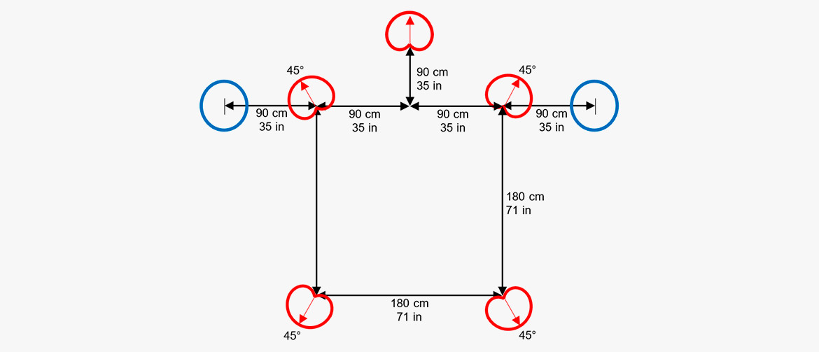
The choice of cardioid microphones improves the channel separation, and the backward-oriented rear cardioids also minimize leakage of direct frontal sound to the rear speakers.
Omnidirectional microphones are often preferred in Decca Tree configurations for music recordings due to their natural sound color and full frequency bandwidth. The two omni outriggers serve this very important component in the Fukada Tree array.
Since first announcing the Fukada Tree arrangement, Akira Fukada has designed a number of positioning modifications to improve front localization, but his choice of microphones remains constant and he continues to use DPA mics for their transparent feel.
Hamasaki Square
The Hamasaki Square consists of four bi-directional microphones arranged in a square.
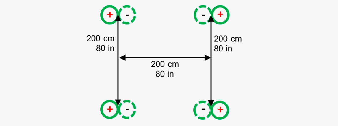
The Hamasaki Square is designed for capturing the ambient/diffuse part of a surround sound recording. It is a four-mic square with 1.8-2 m (5.9-6.6 ft.) between the figure-of-eight microphones, which are routed to left, right, left surround and right surround at an appropriate level compared to the front array. The figure-of-eight microphones are pointed with their in-phase sensitive directions against the sides and with their nulls to the direct sound.
Compared to other systems for ambiance recording, this system is the least sensitive regarding the distance between the main array and the ambiance array.
The setup is defined by the Japanese sound engineer Kimio Hamasaki.
Immersive audio with height
Setups developed for traditional surround recordings (like 5.1) have proven to work very well. However, adding height to these recordings is interesting as it may also add new dimensions to the perceived experience.
The challenge is, however, how to add upward-directed sound images, without changing the perceived localization of horizontally positioned sound sources, meaning minimizing vertical inter-channel crosstalk. This leads to considerations regarding vertical time and level differences. The spacing of vertical microphones needed for decorrelation must also be considered. Finally, how can we avoid comb filtering in the unavoidable downmix?
When height information is added in the right way, the perceived envelopment created by the sound is enhanced. More than that, good practice has demonstrated enhancement of the perceived precision when localizing the sound sources, even in the horizontal plane!
 Examples: A standard reproduction setup for immersive audio containing height information is 9.1, which is a standard 5.1 ITU 775 layout with additional upper-layer speakers above the left, right, left surround and right surround speakers. The height of the additional four speakers should provide a vertical listening angle of approximately 30°.
Dr. Hyunkook Lee of Huddersfield University (UK) and his research group have provided a lot of theoretical and practical information on the perceived sound imaging.
One important factor he found is that the precedence effect (the effect that the first arriving sound determines the direction) does not work in the vertical plane. Hence, it is worth looking at level differences. When playing back the same sound in the lower and the upper loudspeaker, it was found that the presence of higher frequencies and transient signals pulls the localization towards the upper loudspeaker [2,3].
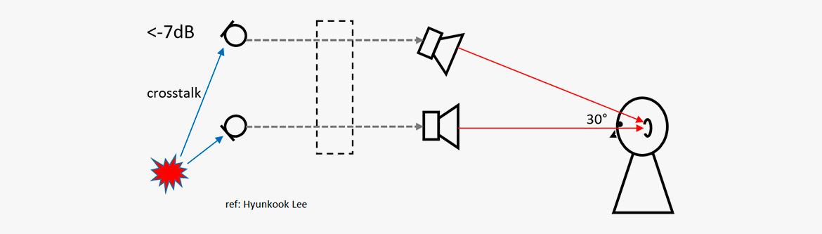 Example: To keep the localization in the horizontal plane, it was found the upper signal should be attenuated by at least 7 dB.
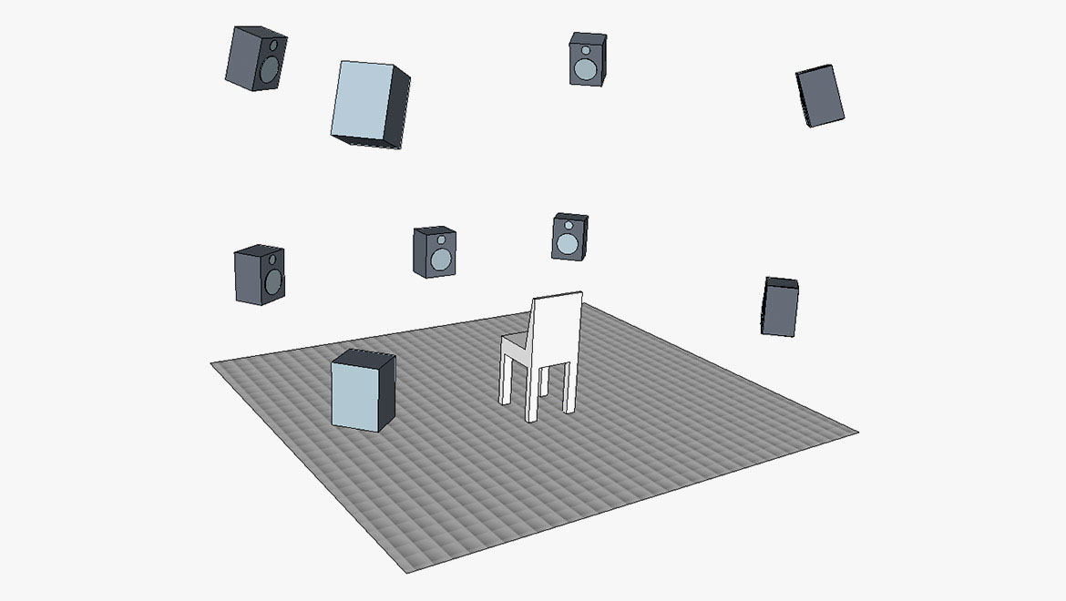
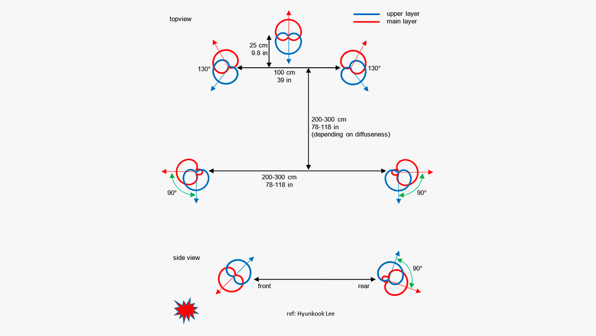
These findings have led to the microphone setup shown below. It consists of eight cardioid microphones and two supercardioid microphones.
The orientation of the microphones is such that there is a minimum of frontal sound entering the upper layer of microphones. In general, any upper-layer microphone should receive as little sound as possible that contains sound from the primary horizontal sources and sources below the horizontal plane.
[1] Wallis, Rory, and Lee, Hyunkook: The Effect of Inter-channel Time Difference on Localization in Vertical Stereophony. Journal of the Audio Engineering Society, Vol. 63, No. 10, October 2015.
[2] Lee, Hyunkook, and Gribben, Christopher: Effect of Vertical Microphone Layer Spacing for a 3D Microphone Array. Journal of the Audio Engineering Society, Vol. 62, No. 12, December 2014.
[3] Lee, Hyunkook: Perceptual Band Allocation (PBA) for the Rendering of Vertical Image Spread with a Vertical 2D Loudspeaker Array. AES Convention 138, Warzawa 2015.
[4] Lee, Hyunkook: The Relationship between Interchannel Time and Level Differences in Vertical Sound Localisation and Masking. AES Convention 131, New York 2011.
IRT Cross
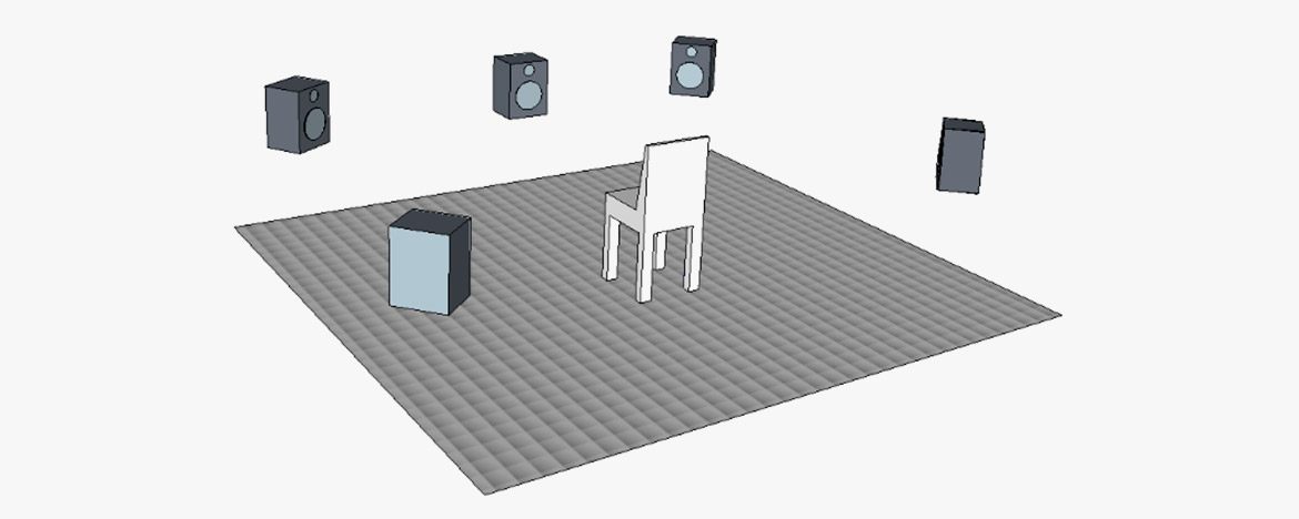
The IRT Cross is designed for ambiance pickup. The setup consists of four cardioid microphones.
The IRT cross is designed for capturing the ambient/diffuse part of a surround-sound recording. It is a four microphone square with 20–25 cm (7.9–9.8 in) between the cardioid microphones, which are routed to left, right, left surround and right surround in an appropriate level compared to a front array.
The IRT Cross is normally positioned a couple of meters behind the main array. However, it should not be placed too far away as there may occur timing problems (like an echo) in the reproduced signal. The optimal placing of the IRT Cross is a balance between getting enough ambiance while at the same time avoiding echo.
Object-Based audio
For years, the most enveloping loudspeaker-reproduced sound has been channel based. One channel is for mono, two channels are for stereo and six channels are for 5.1 surround-sound (or 24 channels for NHK 22.2).
Conventions regarding the placement of the loudspeakers for each format have been the backbone of the sound design. Inter-channel panning by the aid of delay- or level adjustments has been the tool for the placement of sources of the sound scene. The finished product would be contained in a fixed number of channels; even though the program material originally was recorded on a huge number of audio tracks, the final product would fit into a specific number of channels, one for mono, two for stereo, etc.
The Object-Based Audio (OBA) is somewhat different. A "sound object" can be recorded on one or more tracks. Along with the audio goes the metadata that tells where to position the sound in the soundstage.
An object could be a voice recorded in mono. If the producers intend to let the voice come from the right of the soundstage, then the metadata of the voice recording contains the coordinates of this sound. The voice is for this reason recorded as a stereo track. Then the metadata of these stereo tracks provides the data for the positioning.
In principle, an object may also stem from an ambisonic recording or any other format. Therefore, an AV program with OBA is built up from a string of objects, like voice recordings, music, ambient sounds, special sound effects, etc. Each object will contain metadata on when and where to be reproduced.
OBA has already found its way to the cinema (Dolby Atmos and the like). However, it is the intention to bring it into broadcast as well, and many experiments have been carried out. In addition, virtual reality (VR) is an obvious target for OBA.
Why?
The general idea is to leave a higher degree of freedom to the listener, especially in broadcast. Now it is possible to emphasize a single object. If a hearing-impaired listener wants to level up the dialog, this is a possibility, if you record the dialog as an object. You can also change the language of the commentary, if you allocate each language to separate objects.
From TV productions like Formula 1 races, we know that special onboard cameras can be selected, if the viewer wants to follow a specific car. The sound of that specific car is an object in conjunction with the image. Specific musical instruments in an orchestra can be regarded as objects. Alternatively, the sound from a concert, recorded at different listening positions can be objects.
Another argument for OBA is that almost any reproduction format is valid. The downmix is optimized depending on the number of channels and their positions available for the playback (as long as the number of channels is at least two). Binaural reproduction is also allowed for.
Microphones?
The basic idea is that the sound engineer can use the kind of microphones that he likes. There is not necessarily a demand for specific microphones, microphone configurations or microphone brands. The special requirement goes on the production equipment, that can establish the metadata and of course to the formats that carry the complete information.
Suggested microphones & accessories
Omni-based surround array
- 4006A Omni Microphone
- 4006C Omni Microphone, Compact
- 5006A Surround Kit of five matched 4006A microphones, clips and windscreens in Peli™ case
- S5 Surround/Decca Tree Mount
Cardioid-based surround array
- 4011A Cardioid Microphone
- 4011C Cardioid Microphone, Compact
- S5 Surround/Decca Tree Mount
Wide cardioid surround array (WCSA)
- 4015A Wide Cardioid Microphone
- 4015C Wide Cardioid Microphone, Compact
- 5015A Surround Kit of five matched 4015A microphones, clips and windscreens in Peli™ case
- 4006A Omni Microphone
- 4006C Omni Microphone, Compact
- 3506A Kit of two matched 4006A microphones, clips and windscreens in Peli™ case
- S5 Surround/Decca Tree Mount
Optimized cardioid triangle (OCT)
- 4011A Cardioid Microphone
- 4011C Cardioid Microphone, Compact
- 4018A Supercardioid Microphone
- S5 Surround/Decca Tree mount
Double MS
DPA does not provide any figure-of-eight microphones. We suggest the Schoeps MK8 with CMC6 preamp. However, if you want to try this setup with DPA microphones, we suggest you substitute each figure-of-eight microphone with two cardioid microphones:
- ST4011A Stereo Pair with 4011A Cardioids
- SB0400 Modular Stereo Boom
- UA0836 Stereo Boom
- DUA0019 Spacer for Stereo Boom, 19 mm (0.75 in)
Fukada tree
- 4011A Cardioid Microphone
- 4011C Cardioid Microphone, Compact
- 4006A Omni Microphone
- 3506A Kit of two matched 4006A microphones, clips and windscreens in Peli™ case
- S5 Surround/Decca Tree Mount
- ST4011A Stereo Pair with 4011A Cardioids
- SB0400 Modular Stereo Boom
Hamasaki square
DPA does not provide any figure-of-eight microphones. We can suggest the Schoeps MK8 with CMC6 preamp. However, if you want to try this setup with DPA microphones, we suggest you substitute each figure-of-eight microphone with two cardioid microphones:
- ST4011A Stereo Pair with 4011A Cardioids
- S5 Surround/Decca Tree Mount
Immersive audio with height
- 8 x 4011A Cardioid Microphone
- 2 x 4018 Supercardioid Microphone
IRT Cross
DPA 5100 Surround Microphone
The
5100 Mobile Surround Microphone is a plug-and-play solution.
One unit contains three directional (DIP-MIC, directional pressure microphones), coincidently arranged frontal microphones. The rear channels are recorded by a spaced pair of two omnidirectional microphones. The unit also provides an LFE-output. All channels are calibrated to unity gain. The LFE is reduced by 10 dB, according to the standard.
The 5100 is much appreciated in film production for 2nd unit work.
References
[1] Gasull Ruiz, Allejandro: A Description of an Object-Based Audio Workflow for Media Productions. Convention Paper 9570, AES 140th Convention, Paris 2016.
[2] Steven A.: Object-based audio for television production. IBC 2015.
[3] Messonnier, Jean-Christophe et al.: Object-based audio recording methods. Conference proceedings, AES 57th International Conference, USA, 2015.
[4] Shirley, Ben et al.: Personalized Object-Based Audio for Hearing Impaired TV Viewers. Journal of the Audio Engineering Society, Vol. 65, No. 4, April 2017.