When it comes to capturing pristine audio in challenging environments, interference tube microphones - or shotgun microphones - stand out as the go-to solution for professionals in various fields, including film, broadcast, field recording, sports and wildlife sound capture. These specialized microphones are designed to mitigate unwanted noise and deliver excellent sound quality.
In this article, we describe how we can specify the directivity of these microphones. If you want to know more about how they work, please read the Mic Uni-article: The interference tube and its use in microphones.
Describing directivity
When we describe the directivity of so-called first-order directional microphones (wide cardioid, cardioid, super cardioid, etc.), we use the shape of the polar pattern to characterize it. This is possible because all these patterns should stay relatively constant at all frequencies. This is, of course, only sometimes the case, but that is what the designers aim for.
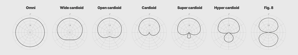
Figure 1: 1st order polar patterns in logarithmic presentation (dB-scale).
We record a polar pattern under anechoic (reflection-free) conditions. To do this, the microphone is mounted on a special turntable. Then, a tone generator creates the test signal through a loudspeaker placed at a distance at same height as the microphone. As the microphone rotates, the output signal is recorded continuously, or per, say, 5°.
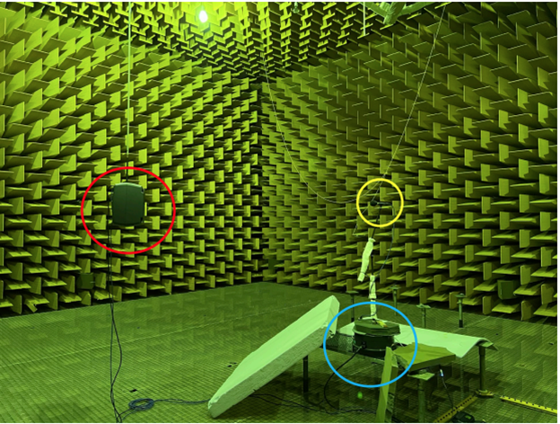
Figure 2: DPA setup in an anechoic chamber at the Technical University of Denmark. Yellow circle: Microphone. Red circle: Loudspeaker. Blue circle: Turntable.
There are two ways to measure a polar pattern. It can be measured using pure tones (sine waves) at one specific frequency or averaged over a number of frequencies within a given range, i.e., per octave band or 1/3 octave band.
Alternatively, it can be measured using noise (for instance, pink noise), which contains all frequencies produced simultaneously and then filtered in octave bands or 1/3-octave bands.
High-quality, first-order mics will only present minor differences between the methods, as their patterns are roughly constant or only slightly changing throughout the frequency range.
First-order polar patterns are easy to read as the microphones' acceptance angle (the angle inside which the pickup only drops by 3 dB, also called the opening angle) are easy to see if the scale is appropriate. It is most important in the 1-4 kHz frequency range. Usually, the acceptance angle is defined at 1 kHz if nothing else is stated.
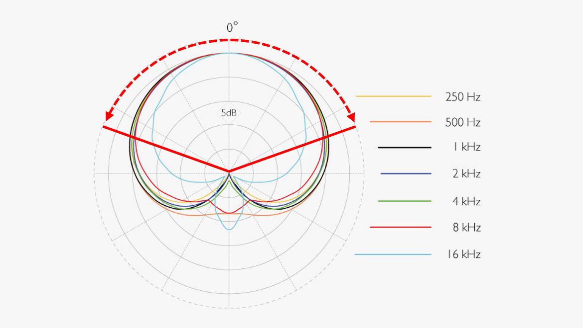
Figure 3: 1st order cardioid polar patterns with marking for acceptance angle (-3 dB re 0° @ 1kHz).
Studying first-order polar patterns, we can see the frontal pickup lobe and perhaps a back lobe if the microphone is more directive than a cardioid. In the case of the figure-of-eight pattern, the front and the back lobes are equal in size.
However, the polar plot becomes lobar at high frequencies when we look at the response of the interference tube microphones. "Lobar" or "lobe-shaped pattern" means the polar plot now exhibits more than two lobes.
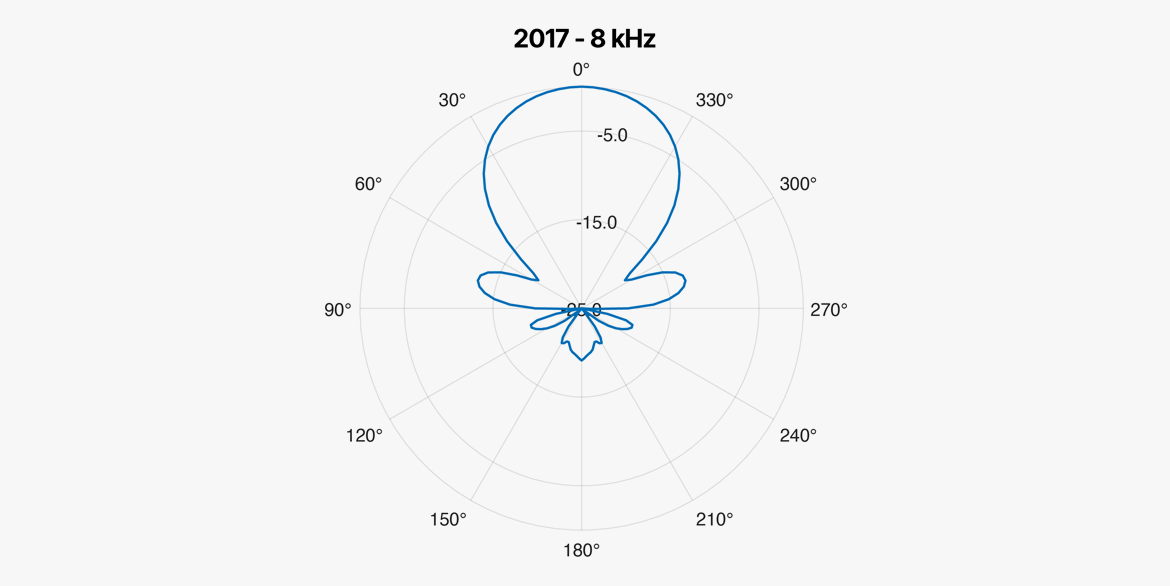
Figure 4: Example of lobar polar plot.
It can become very messy to read polar plots with many lobes. Further, it does not sound what it looks like unless you listen to pure tones. The sound experienced as a broad or narrow band signal might differ significantly from the information displayed in a polar plot based on single sine waves.
From a psychoacoustic perspective, using noise or averaged frequencies in octave bands or fractions of octave bands is better for directivity measurements (especially for shotgun microphones). The averaged plots are more related to the perception. However, this is a matter of taste and practice as long as you are informed about the measurement conditions.
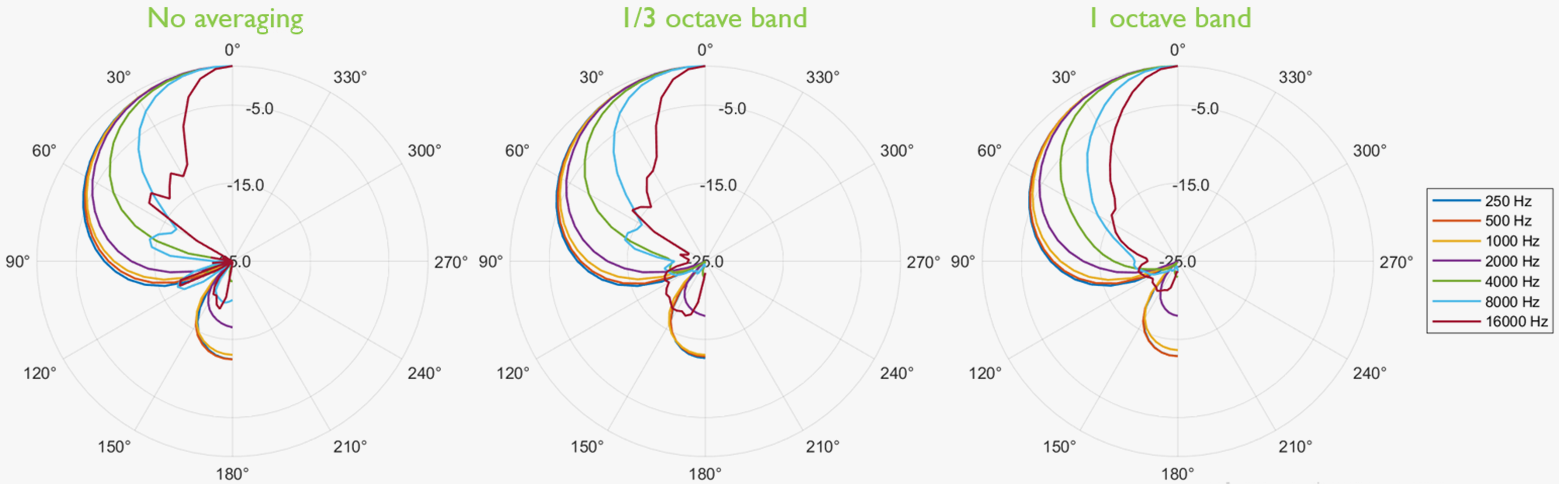
Figure 5: Example of same shotgun measured with pure tone and averaging 1/3 octave and 1/1 octave band.
Distance Factor (DSF), Directivity Factor (DF or Q), and Directivity Index (D or DI)
Besides polar plots, other terms for directionality include Distance Factor, Directivity Factor, and Directivity Index. Using these three "factors" to describe microphones' directivity may seem somewhat confusing. However, they become meaningful if we take a closer look.
Distance Factor
The distance factor (DSF) roughly describes how far away we can position a directional microphone compared to an omnidirectional microphone to maintain the direct-to-diffuse field ratio. It can be considered the "reach" of a microphone in a reverberant environment.
Imagine a sound source and a microphone in a room. Suppose the distance from the sound source to an omnidirectional microphone is 1. In that case, a cardioid microphone can be positioned 1.73 times from the sound source to achieve the same balance between direct and diffuse sound (given that the microphones have the same sensitivity).
Therefore, a cardioid mic’s distance factor (DSF) is 1.73. The distance factor is related to the signal's amplitude.
See the diagram below for other distance factors.
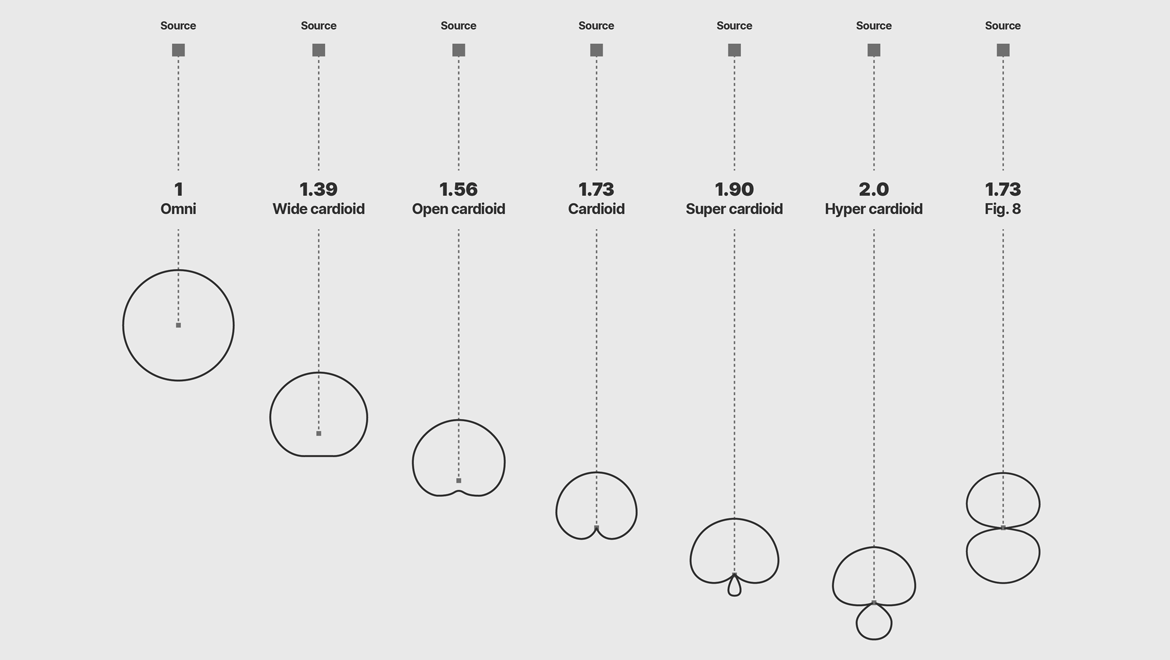
Figure 6: Distance factor (DSF) of 1st-order microphones.
Directivity Factor
The directivity factor (DF or Q) is defined as the ratio of the energy picked up on-axis to the energy picked up in all directions.
Directivity Index
The directivity index (D or DI) is the directivity factor (DF) in dB: (DI = 10* log DF).
The table below shows the polar pattern name and the associated DSF, DF, DI, and Acceptance Angle.
|
Polar pattern
|
Distance factor
(DSF)
|
Directivity Factor
(DF)
|
Directivity Index
(DI)
|
Acceptance angle
(-3 dB)
|
|
Omnidirectional
|
1.00
|
1.00
|
0.0
|
360°
|
|
Wide cardioid
|
1.39
|
1.92
|
2.8
|
177° (±88.5°)
|
|
Open cardioid
|
1.56
|
2.42
|
3.8
|
149° (±74.5°)
|
|
Cardioid
|
1.73
|
3.00
|
4.8
|
131° (±65.5°)
|
|
Supercardioid
|
1.93
|
3.71
|
5.7
|
115° (±57.5°)
|
|
Hypercardioid
|
2.00
|
4.00
|
6.0
|
105° (±52.5°)
|
|
Figure-of-eight
|
1.73
|
3.00
|
4.8
|
90° (±45°)*)
|
Table 1: Polar pattern vs. DSF, DF, DI, and acceptance angle.
*) The figure-of-eight also has a similar acceptance angle to the rear).
Directivity of interference tube microphones
As mentioned, in principle, the interference tube microphone consists of the 1st-order cardioid element and the tube.
Ideally, the directivity of the cardioid is constant with frequency, whereas the interference tube increases directivity with frequency.
Looking at the design may leave the impression that the outer tube and its slits create interference. However, it is actually the inner mesh and its density that are responsible. The outer tube is a hard shell that protects the soft inner mesh. That said, the outer tube must have slits all the way around. If not, the directivity may change with the rotation of the microphone.
Combining the two components yields a constant directivity up to a particular frequency and a raise above the corner frequency of the directivity. As the interference tube gets longer, the corner frequency gets lower. In general, longer interference tubes provide higher directivity. However, the mesh's density also influences directivity; this is one reason, although the 2017 Shotgun Microphone looks shorter than others, it still provides high directivity.
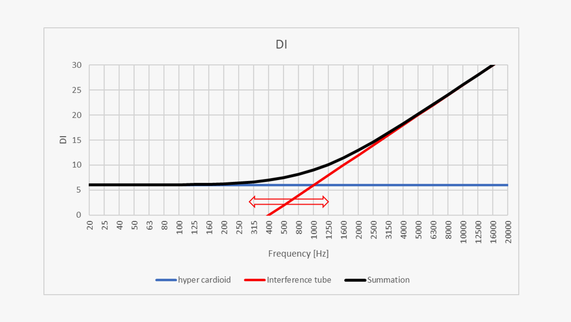
Figure 7: Theoretical directivity response of a shotgun (black curve); here, an ideal hypercardioid (blue curve) combined with the interference tube (red curve).
Shotgun mics exhibit a directivity that changes with frequency. This is why it is problematic to name the directivity of a shotgun after standard polar patterns like, e.g., supercardioid. This term would only be valid up to a particular frequency. Instead, it is better to express the directivity as DI vs. frequency either in a curve or in numbers.
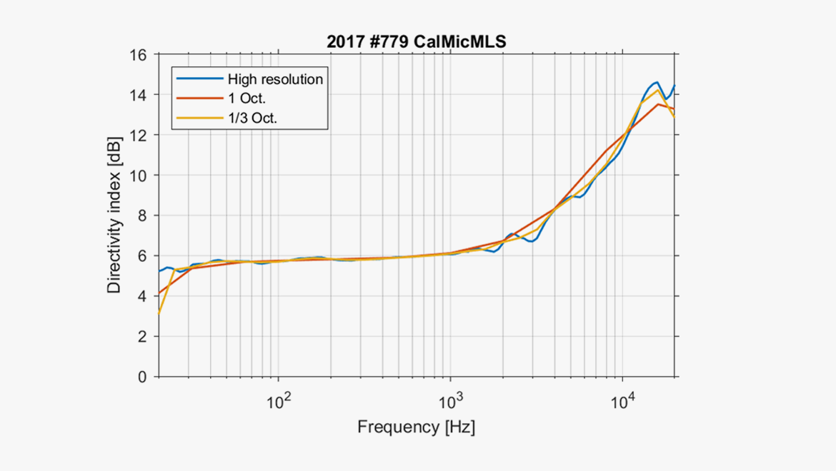
Figure 8: DI vs. frequency of 2017 Shotgun Microphone (High resolution, 1/3-octave band, and 1/1 octave resolution.
|
|
63 Hz
|
125
|
250
|
500
|
1k
|
2k
|
4k
|
8k
|
16k
|
|
DI
|
6
|
6
|
6
|
6
|
6
|
6.6
|
8.2
|
11.2
|
13.3
|
|
Acceptance angle (-3 dB)
|
105°
|
105°
|
105°
|
105°
|
105°
|
90°
|
80°
|
50°
|
25°
|
Table 2: 2017 Shotgun Microphone’s DI and acceptance angle vs. frequency. (The built-in high-pass-filter makes 63 Hz irrelevant).
Conclusion
There are several ways to specify directivity.
Standard 1st-order microphones are usually described by their polar pattern - cardioid, supercardioid, etc., because their directivity is fairly constant with frequency. For these mics, it is easy to read the polar plot and the acceptance angle.
Shotgun microphones – or interference tube microphones – can better be described by the directivity index (DI) as these microphones increase the directivity from a given frequency and up.