Wisycom
Microphone technology - the essentials
The microphone is an electroacoustic device that converts acoustic energy into electrical energy. This conversion occurs via a mechanical system, usually a diaphragm, set into oscillations by a sound field. The mechanical movement is then converted into an electrical signal by an electromechanical coupling.
Sound as a physical phenomenon is, in principle, described by either sound pressure, particle velocity or sound intensity. Most microphones react to the sound pressure, the sound-pressure gradient or a combination of both. Therefore, this section on microphones will only deal with these types:
- Pressure microphones
- Pressure gradient microphones
- Combinations of pressure and pressure gradient microphones
The above classification does not refer to conversion from acoustic energy to electricity. Thus, further, a division is made:
- Dynamic microphones
- Condenser microphones
- Digital microphones
Crystal microphones, heating wire microphones and carbon microphones are not described here, as they do not play any role in professional audio.
Pressure microphones
A pressure microphone is, in principle, a diaphragm in front of a closed chamber. The sound pressure can only reach the diaphragm from one side.

Figure 1. Principle of a pressure microphone – a diaphragm in front of a closed chamber (without a transducer).
A pressure microphone can be compared to a pressure gauge for measuring pressure in liquid, measuring it as a scalar value without direction. It does not matter which direction the membrane faces. It is the pressure at the actual depth that counts.

Figure 2. Principle of a pressure transducer.
Similarly, a pressure microphone will detect sound pressure no matter from which direction the sound enters. A pressure microphone is omnidirectional.
However, the microphone's physical dimensions will influence the sound field in which it is placed. At higher frequencies, with wavelengths that are comparable and shorter than the diaphragm diameter, a pressure build-up occurs when on-axis sound hits the diaphragm. The result is increased output from the microphone.
Conversely, when the sound comes from the microphone's back side, a particular shadowing effect will occur. The degree of influence from these phenomena depends on the dimensions of the microphone. The larger the diaphragm and microphone housing dimensions, the further down in the frequency range it will exhibit increased sensitivity.
So, if sound can only reach the diaphragm from the front, it is a pressure microphone, and therefore, omnidirectional.
Pressure gradient microphones
In a pressure gradient microphone, sound pressure can reach the diaphragm from both front and back. The output voltage from a microphone is proportional to the pressure gradient, i.e., the pressure difference between the diaphragm's front and back. If sound comes from the side, the same pressure exists on both sides of the diaphragm. Then there is no gradient and thus no signal out of the microphone.

Figure 3. Principle of pressure gradient microphone.
A pressure gradient microphone is bi-directional and exhibits a directional characteristic of a figure 8. As with pressure microphones, pressure gradient microphones' characteristics are also closely linked to the sound field in which they are placed.
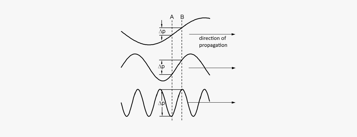
Figure 4. Pressure gradient at various wavelengths.
The difference in sound pressure depends on the wavelength of the sound. Deep tones, i.e., frequencies with a long wavelength, longer than the distance between the diaphragm's front and back, give only a small pressure difference. With increasing frequency, the gradient increases, and by that the diaphragm movement increases. The maximum diaphragm movement is achieved at the frequency where half the wavelength is equal to the distance between the diaphragm's front and back.

Figure 5. Pressure gradient between two points of a soundwave.
With standard-sized microphones, this happens at approximately 5-10 kHz. At shorter wavelengths, the conditions become further complicated, and the figure 8 characteristic must be supported by mechanical designs that provide shadow or interference effects.
The “raw” frequency response of a pressure gradient microphone lacks bass. The slope of the curve is +6 dB/octave. To make the microphone exhibit a proper low-frequency response, different techniques are used in the design to provide flat frequency response. One approach is to make the diaphragm more sloppy, resulting in a low resonance (just like tuning a drum). Depending on the design and the need for sensitivity there is a roll-off, which is 12 dB/octave below this resonance. All gradient microphones exhibit a low-frequency roll-off at some point.
With pressure gradient microphones, there is also another factor that comes into play. If the sound source is positioned close to the microphone, a bass-lift occurs. This phenomenon is called proximity effect. This effect is due to the inverse square law (the law of losing 6 dB per distance doubling from a point source). This effect comes into play at short distances.
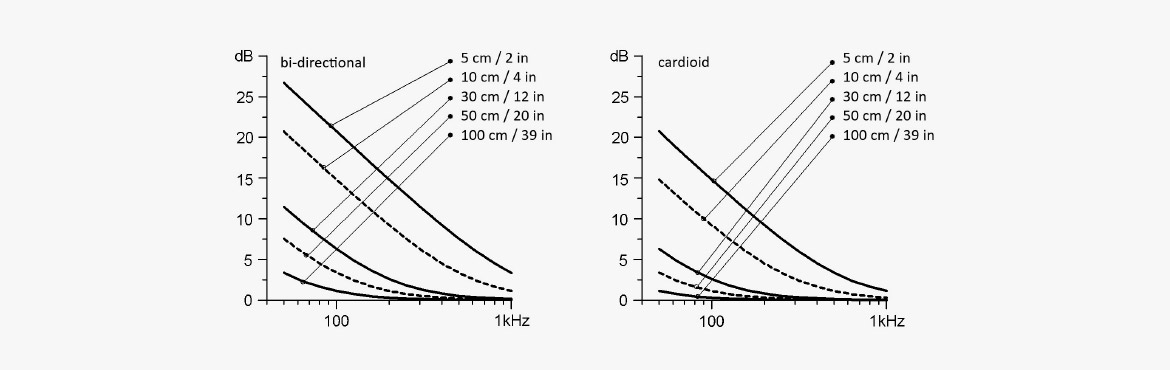
Figure 6. The effect of proximity: Bass lift versus distance to sound source, bi-directional and cardioid microphones.
If, for example, a point source is located 2 cm from a diaphragm and the distance from the front to the backside of the diaphragm is also 2 cm, the pressure difference will be 6 dB. This difference principle applies to the entire frequency range. However, as the pressure gradient is low at low frequencies, the effect of the additional pressure difference result in increased low-frequency output. In other words: When the sound source gets closer to the microphone, the sound gets more bass.
Combined pressure and pressure gradient microphones
If you combine pressure and pressure gradient principles, you get a directional microphone – including wide cardioid (subcardioid), cardioid, supercardioid and hypercardioid characteristics.
The coupling of the two principles can take place either mechanically-acoustically or electrically.
Using a mechanical acoustic coupling, the part of the sound that affects the back of the diaphragm is passed through one or more openings of the microphone housing. By varying the size and attenuation of these openings, it is possible to control the characteristics from omnidirectional (fully enclosed microphone housing) to bi-directional (sound can access both the front and back of the diaphragm). This form of coupling can apply to both dynamic and condenser microphones.

Figure 7. This microphone housing allows sound to enter the rear opening, providing a pressure gradient.
By partially closing the back of the diaphragm, the opening is covered with porous or perforated damping material so that that sound can pass at a reduced speed. This technique ensures that sound coming from the rear (180° re on-axis direction) reaches the diaphragm's front and back simultaneously. This results in no diaphragm movement and the microphone behaves as if it is insensitive to sound from behind. At other sound directions (¹≠180°), the diaphragm will have increased sensitivity. This microphone has cardioid characteristics.
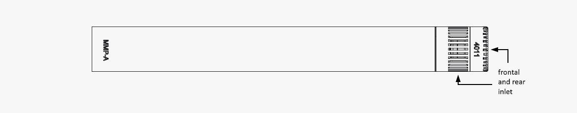
Figure 8. Example of combined pressure and pressure gradient microphone.
By changing the attenuation of the sound's access to the diaphragm's back to a certain degree, the microphone becomes insensitive to sound incidence from an angle of 120° off-axis. This is a supercardioid microphone design, which is slightly sensitive to sound coming directly from behind.
The electrical coupling between the pressure and pressure gradient principles is usually only done with condenser microphones. This type of coupling is easy to make variable and will be described in the section on condenser microphones.
The microphone in the sound field
Due to the presence of the microphone in the sound field, at high frequencies, it will have a disturbing influence on the field. There will be a partial bending around the microphone – diffraction – as well as a partial reflection from the front of the diaphragm with pressure build up as a result.

Figure 9. Pressure build-up at wavelengths equal to and shorter than the diameter.
Pressure microphones are most affected by their physical dimensions. Their spherical characteristic changes with increasing frequency to a narrower characteristic. At the same time, pressure accumulation occurs, which is why the frequency response will show a rise of several dB in the axis direction at high frequencies.
The basic design of pressure microphones often exhibits a roll-off at higher frequencies. When adding a grid in front of the diaphragm, this cavity has a resonance that lifts the higher frequencies to obtain the flat free-field response, or the flat diffuse-field response needed.
Also, various accessories may be used, such as acoustic pressure equalizers (APEs). These devices further increase the frequency response and directivity.
A pressure gradient microphone with a figure 8 characteristic can be constructed without diffraction problems up to their cut-off frequency. Above the cut-off frequency, diffraction and pressure build up can partly correct the decreasing frequency characteristic.
When recording sound in rooms, at a distance (e.g., 1-2 m) from the sound source, the perceived sound, in addition to the direct sound field, is significantly affected by the diffuse field.
A typical design goal for pressure gradient microphones is to make the free-field characteristic and the diffuse-field characteristic run as parallel as possible with the frequency. This allows you to change the "spatial effect", i.e., the ratio of direct sound and reflected sound, to the recording, without changing the frequency balance of the microphone.
With pressure microphones, one must choose either a flat free-field characteristic or a flat diffuse-field characteristic. This can be done by choosing between different front grids for the microphone.
Special directional microphones
In certain situations, microphones with a stronger directionality may be needed than what a cardioid or supercardioid microphone can offer.
Interference tube microphone
An interference tube microphone is particularly useful when focused directionality is needed. They are often referred to as a "gun" or "shotgun" microphone. An interference microphone can be formed as several parallel tubes of different lengths arranged perpendicular to the microphone element. Most commonly, however, is a single, mesh tube, protected by a slitted hard-shell tube.
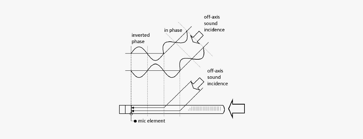
Figure 10. Interference tube microphone.
Common to both designs is the principle of operation: When sound hits the microphone directly on-axis, the individual parts of the sound wave will travel equal distance. Thereby they reach the pressure-sensitive element simultaneously and thus stay in-phase.
If the sound hit the microphone from other angles, the individual parts of the sound wave will travel through different paths to reach the pressure-sensitive element. The individual pressure contributions can therefore not have the same phase and, when added together, will form a sound pressure that is considerably less than that which was formed by the direct sound incidence.
This phasing out of sound incidence from the side will depend on the wavelength of the sound wave in question and the angle at which the sound incidence occurs.
Since the modern interference microphone is designed as a long tube with slits along the entire length of the tube, it provides a more uniform attenuation of sound input from the side than a limited number of tubes can provide. However, an acoustic attenuation of the sound waves that have incidence closest to the pressure-sensitive element must be performed. Therefore, it is not just a question of making a slotted tube, but also a question of having suitable damping in the tube.
Since interference in a tube will first occur for tube lengths greater than half the wavelength, the high directional effect can only be obtained in the upper part of the frequency range. Therefore, the microphone element (without tube) is often a cardioid microphone to achieve some directional effect at the low frequencies.
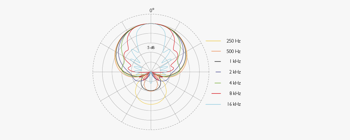
Figure 11. Directional characteristics of an interference tube microphone.
An interference tube microphone is predominantly sensitive in one direction; however, it is full of side lobes. In many cases, the frequency characteristics outside the microphone axes become incredibly uneven. The sound coming from here will inevitably be colored less nicely.
Zoom microphones
By design, zoom microphone achieves a variable directional factor. This is done by assembling two microphone elements in the same house. One is created as an interference microphone and thus has high directivity. The other can be a pure 1st order pressure gradient microphone having cardioid characteristics.
By gradually shifting from one microphone to the other, a variable directional characteristic is obtained that is acoustically reminiscent of the photographic zoom function. However, a zoom microphone has its limits as the maximum directivity factor achievable is 2.
Parabolic screen
It is possible to obtain an increased directional effect for a microphone by placing it in the focal point on a parabolic screen. It is a principle used mainly by those involved in recording bird song. However, sports broadcasts also take advantage of this screen.
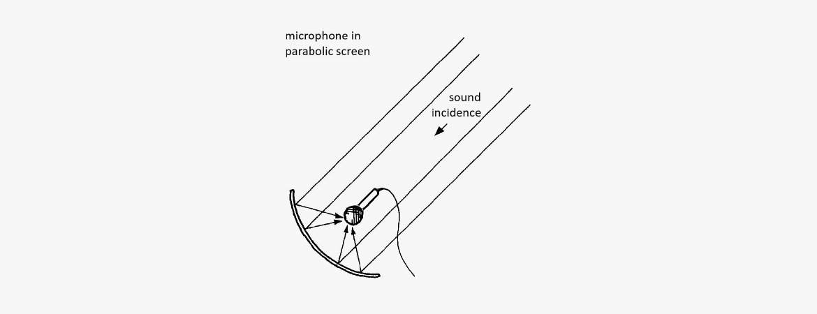
Figure 12. Microphone in the focus of a parabolic screen.
As the parabolic screen must not be too large for handling reasons, it also implicates a lower limit for frequencies that can be reflected and thus amplified. In practice, the limit is somewhere between 500-1000 Hz. Below this frequency, the microphone will behave as if there were no screen.
Boundary layer Microphone
A boundary layer microphone (BLM) is, in principle, an ordinary microphone element that is used acoustically in a particular way.
As the name implies, this microphone is placed at the boundary layer or pressure zone.
If a sound hits a hard surface, the sound is reflected. Therefore, a pressure build-up occurs very close to the reflecting body, which can be registered by the microphone as a pressure increase. Thus, the pressure at the surface is 6 dB stronger than it would have been without a reflective surface. Furthermore, the diffuse sound is gained only by 3 dB.
By placing a microphone directly on the reflecting surface, a 6 dB louder signal is obtained. The microphone's ability to draw in distant sound sources is due to the 3 dB improvement of the free field-to-diffuse field ratio.
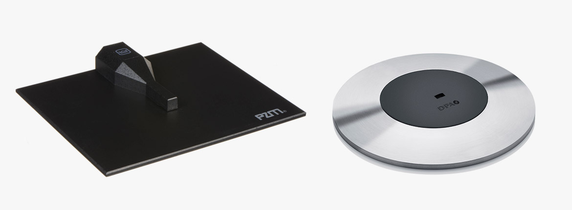
Figure 13a. Boundary layer microphones.
Basically, the boundary layer microphone is a pressure type. However, it is also possible to use a directional microphone element if it is positioned extremely close to the reflecting surface.
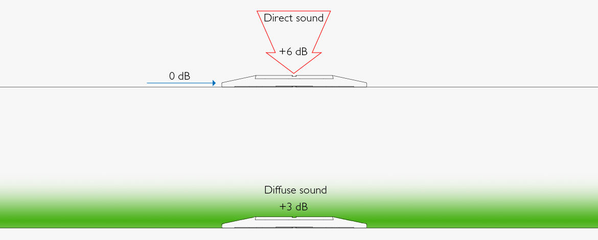
Figure 13b. Direct and diffuse sound field at Boundary layer mic.
Application of signal processing
When special properties are desired, for example regarding directional characteristics, digital signal processing can be used to advantage.
An example of this is KEM (Kardioid - Ebenen - Mikrofon), which has been developed by the Institut für Rundfunktechnik. The microphone acts as an inverted column speaker. An array of microphone elements delivers signals, and summation/filtering in the subsequent digital process results in a directional characteristic that can almost be said to be "flat as a pancake".

Figure 14. KEM (Kardioid Ebenen Mikrofon) Microtec Gefell.
Beamforming is obtained by processing the signals from many elements placed in a row behind each other or on a larger surface (i.e., ceiling microphones, 600 x 600 m).
The converting principle
Until now, we have only dealt with how a sound field has affected the microphone diaphragm. Next, we should investigate how diaphragm movement is converted into an electrical signal.
In professional audio, microphones are divided into two main groups:
Dynamic microphones
- Moving coil microphones
- Ribbon microphones
Condenser microphones
- LF condenser microphones
- HF condenser microphones
- Electret microphones
- (Digital microphones)
Dynamic microphones
Dynamic microphones work according to the induction principle. An electric conductor moves due to the sound in a magnetic field. This induces an electrical voltage across the endpoints of the conductor, which is proportional to the speed of the conductor in the sound field. The output signal is thus 90° out of phase with the sound pressure at the diaphragm.
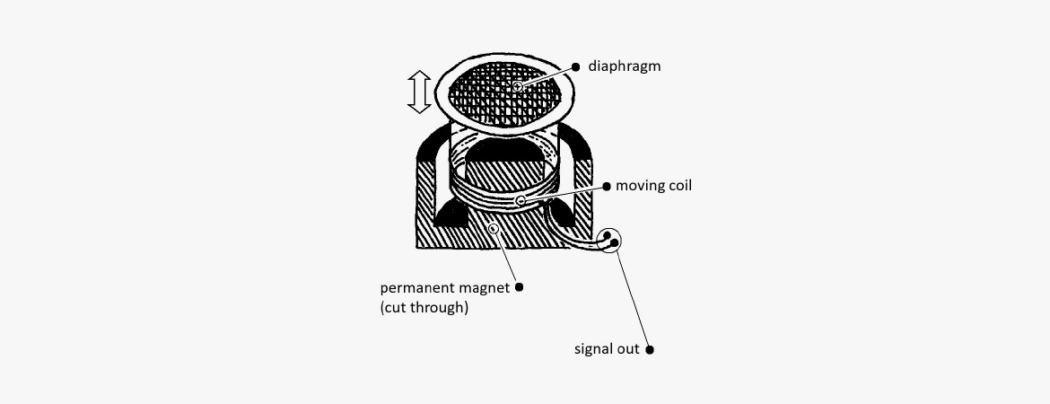
Figure 15. Principle of moving coil microphones.
Moving coil microphones
In a moving coil microphone, the conductor is designed as a small coil attached to a membrane of plastic or metal. The coil is positioned in the air gap of a strong circular permanent magnet. The construction is very similar to the electrodynamic loudspeaker.
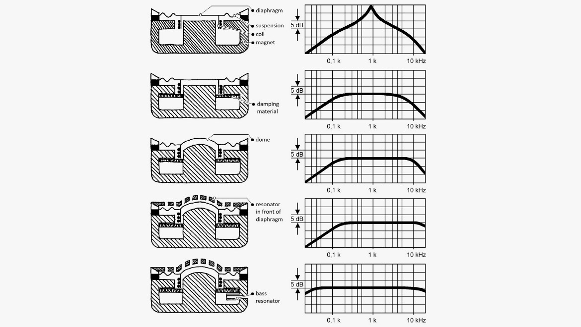
Figure 16. Control of resonance phenomenon in dynamic voice coil microphones.
You can compare the electrodynamic microphone to a mass/spring system. The mass is formed by the diaphragm and the voice coil, while the suspension acts like the spring. Like the mechanical system, the microphone will also have a resonant frequency. For voice coil microphones, this resonance is between approximately 150 and 800 Hz, i.e., right in the middle of the usable frequency range. It is necessary to dampen the diaphragm to achieve a reasonably flat frequency response. Usually, this is done by inserting damping material.
Over the years, microphone manufacturers have had to experiment with the right mechanical designs to achieve a wide frequency range. By adding damping materials, cavities, ducts, etc., usable results have been reached. However, a moving coil microphone will almost always add something to the sound due to the resonance phenomena. This is one of the reasons why microphones can sound so different.
Ribbon microphones
In a ribbon microphone, the sound field acts directly on the conductor, typically designed as a thin metallic tape. The band is suspended between the poles on a strong permanent magnet.

Figure 17. Ribbon microphone.
When the ribbon moves, voltage is generated across the ends of the ribbon. Both voltage and impedance are very low, so the ribbon is connected to a transformer built into the microphone itself.
The ribbon mass is small, often less than 0.5 mg. The suspension is incredibly soft, which leaves the system with a resonance in the range of 20-70 Hz. Therefore, it is not, as with moving coil microphones, the damping that determines the frequency response, but the mass.
If the sound reaches both sides of the ribbon, it is a pure pressure-gradient microphone with figure 8 characteristics. The polarity of the two lobes is opposite each other.
Ribbon microphones can also couple acoustically, obtaining other directional characteristics.
Ribbon microphones are generally quite sensitive to mechanical impact and wind exposure due to the loosely suspended ribbon. In return, they have a relatively good transient reproduction.
Condenser microphones
H3: LF condenser microphones
An LF condenser microphone consists of an electrically conductive diaphragm stretched out in front of a fixed backplate/back electrode. When supplying the diaphragm and back electrode with a bias voltage, an electric field is created between the two parts, similar to a capacitor's plates. This field tightens the diaphragm.

Figure 18. Principle of a condenser microphone.
When exposed to sound, the distance of the diaphragm to the back electrode will vary. I.e., the capacity will vary with the sound field. Since the charge through the electrical bias is kept constant, the capacitor microphone's instantaneous voltage is proportional to the diaphragm's displacement from the neutral position.
The membrane can consist of a thin metal foil, e.g., nickel, with a thickness of 2-3 µm. Modern condenser microphones have membranes of a plastic foil with a vapor-deposited metal layer of, e.g., gold. These materials result in small mass; however, it may be necessary to support larger diaphragms at their center, so the membrane and backplate will not collapse and short circuit the static voltage.

Figure 19. Double diaphragm condenser microphone.
There is also resonance in the condenser microphone system, but it is significantly higher up in the frequency range than is the case for the dynamic microphone. The diaphragm's damping usually takes place due to the air lying between the diaphragm and the back electrode.
Due to the microphone capacitor's low capacitance (~ 50 pF), the system is very high impedance. Therefore, it is necessary to place an amplifier stage close to the microphone system to have the signal adapted in level and impedance to cables and subsequent inputs. The resulting impedance is usually between 20 and 200 Ω.
The sensitivity of the capacitor microphone depends on the polarization voltage. Therefore, it is possible to obtain different directional characteristics by controlling the polarization of either two separate capsules or two membranes placed on each side of a common electrode.
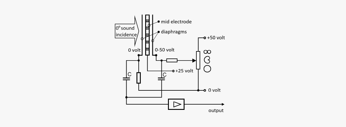
Figure 20. Circuitry for a double diaphragm condenser microphone with switchable directional characteristics.
Figure 20 shows how to get the three main characteristics: omni, cardioid, and figure 8. Any pattern in between is also possible:
Front diaphragm 0 V
Center electrode 25 V
Rear diaphragm 0 V
Both membranes have the same potential, 0 volts, relative to the +25 volts of the center electrode. This configuration results in two cardioid patterns, oppositely directed but in phase. By electrically summing the two signals, spherical directional patterns are obtained.
Front diaphragm 0 V
Center electrode 25 V
Rear diaphragm 25 V
There is no potential difference between the center electrode and the rear membrane, which will be inactive. What remains is the cardioid characteristic of the frontal diaphragm.
Front diaphragm 0 V
Center electrode 25 V
Rear diaphragm 50 V
There is a voltage potential of 25 volts on both diaphragms compared to the center electrode. However, since one is negative while the other is positive, the two systems' signals are oppositely phased, which results in the figure-of-eight characteristic.
HF condenser microphone
In addition to the microphone capacitor, the HF condenser microphone contains a high-frequency oscillator and a demodulator circuit. Unlike the LF condenser microphone, no polarization voltage is applied to the capacitor.
On the other hand, the capacitance variation caused by the sound modulates the oscillator's high frequency, which can typically be around 8 MHz.

Figure 21. Principle of RF-condenser microphone.
The demodulator circuit then detects the LF signal. Only a few brands apply the HF condenser microphone principle. However, it has certain advantages as it is relatively uncritical regarding humidity and isolation failures.
Electret microphone
The Electret microphone basically functions as an LF condenser microphone. However, unlike this, the electret microphone does not have to apply an external voltage across the capacitor plates.
The electret microphone includes materials that are electrically polarized in advance, analogous to a permanent magnet. Materials with these properties can be either plastic foils (polyester, PVC, Teflon) or ceramic electret materials. The polarization takes place by placing the material in a heated state and during subsequent cooling in an electrostatic field, which for the foils constitutes approx. 20 kV / cm. When removing the field, the material will retain a charge corresponding to a polarization voltage, for example, of the order of 100 V. Polarization may also occur, even without applying the heat. If the electric field is strong enough, heating may not be necessary.
The foils may apply as a membrane, and the ceramic electrode material can function as a back-electrode (back electrode microphones).

Figure 22. Principle of an electret microphone.
When a battery or other external voltage is still required for such a microphone, it is due to the built-in amplifier (impedance converter), which requires a supply voltage.
The electret materials have become so good at holding the static voltage that they are even used in measurement microphones, where otherwise there are great demands for stable sensitivity.
Digital microphones
In practice, there are three possibilities:
- Analog microphones with built-in AD converters
- Analog microphones with associated digital signal processing
- Semiconductor Microphones (not mentioned here)
Analog microphones with built-in AD converters
It is this group of microphones that essentially bears the term digital microphones. The acoustic sound is analog, and so is the microphone capsule used. The system is based on the signal being converted to digital code immediately after the capsule with a converter built into the microphone housing itself.
The digital code and the physical part of the interface are based on the AES3 standard. In 2001, a standard was published for the interface that is intended to be used in connection with this group of microphones: AES 42-2001 (current version AES42-2019). The standard is generally accepted, and it is expected that all digital microphones used in professional sound production will live up to the standard.
Principle
The existing microphones place the converter immediately after the microphone capsule, which is of the condenser type. An attenuator that ensures attenuation of the microphone will usually also be located before the converter. In a condenser microphone, an attenuator is constituted by a capacitor inserted parallel to the capsule, whereby the charge of the capsule is reduced with reduced sensitivity.
The built-in converter must be able to handle the overall dynamics of the microphone. Good microphone capsules can have a dynamic range of 125-140 dB, which therefore places at least the same requirements on the converter. In practice, solutions have been seen where a kind of cascade coupling of two converters must be made to be able to achieve the necessary dynamics.
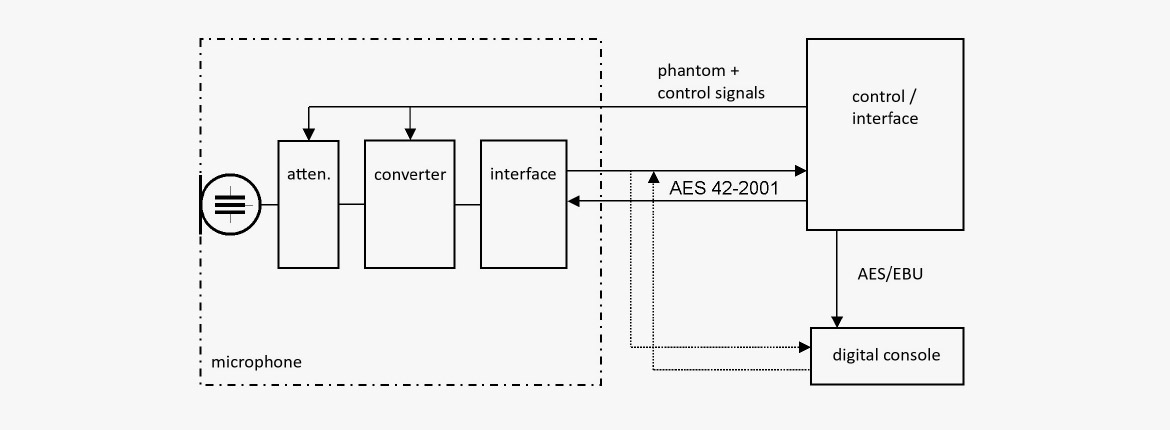
Figure 23. Principle of a digital microphone.
Interface
To talk to the outside world, the output of the converter must be formatted to a standardized interface. AES42-2019 is based on the already known AES3. This is a serial interface where audio data from two channels can be transmitted together with various useful status information such as current sampling frequency, time code, definition of analog reference level etc. The signal can be routed in a two-wire cable equipped with XLR connectors.
AES42-2001 can similarly transmit two signals serially in a two-conductor cable. The interesting thing is that at the same time remote control signals can be transmitted to the microphone together with phantom voltage to supply the microphone. In this way, it becomes possible to set attenuation, directional characteristics, filtering and different signal processing via control box or mixers prepared for digital microphones. Of course, it requires that the microphone contains these options.
The AES42-2019 signal can be fed to a particular remote-control box or to a mixing device if this otherwise has a digital microphone input with the option to control the individual parameters.
The digital synchronization will usually require an external master clock, not least if more than one digital microphone is to be used.
Analog microphones with digital signal processing
When special properties are desired, for example regarding directional characteristics, digital signal processing can be used to advantage.
An example: Townsend Labs Sphere is a double-membrane microphone that can be controlled by a digital plug-in. In the plug-in, the individual diaphragm signals are processed to imitate the characteristic sound of various microphones.
Another example of digital processing applies to an array microphone like the Eigenmike from MH Acoustics. This microphone contains 32 analog capsules (electret) arranged on the surface of a rigid sphere.