Wisycom
About balanced and unbalanced lines
Balanced lines provide better rejection of electromagnetically induced noise. This article explains the difference between signal balanced and impedance balanced lines.
When connecting a microphone to an input a circuit is created. In the unbalanced connection the cable shield is a part of the circuit. Unfortunately this does not provide sufficient isolation to electromagnetic noise present in the surroundings. When using balanced lines, the shield is not a part of the circuit. Induced electromagnetic noise is rejected due to the common mode, the fact that the impedance is exactly the same between each leader and ground. This is called common mode rejection.
Signal balancing
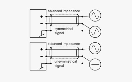
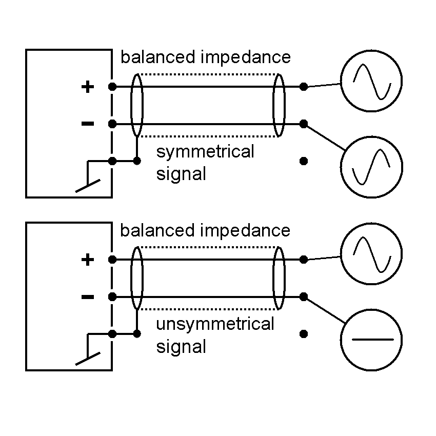
Signal balancing can either be achieved by electronic balancing or by using a transformer. Both ends are hot, but one with reversed phase. At the same time the impedance from each wire to ground is exactly the same. If this is NOT the case, the line is not balanced. And with reference to microphones: Phantom power cannot be supplied.
Impedance balancing
The impedance balancing does not necessarily involve signal balancing. The explanation for this is that the impedance between pin 2 (in the 3-pin XLR) and ground is equivalent to the impedance between pin 3 and ground. But the signal is only present on pin 2. Pin 3 is the reference like in the unbalanced coupling. Hence the impedance is in balance, but not the signal.
The advantage of using an unbalanced signal in an impedance-balanced coupling is that the size (amplitude) of the signal will remain constant, independent of the input connection being balanced or unbalanced, with or without an input transformer.