Wisycom
Your first wireless system - a guide to everything you need to know
This guide covers the fundamentals that make or break a wireless mic setup: antenna placement, line of sight, RF signal strength, frequency selection and battery management.
Congratulations! Installing your first wireless microphone system is a major step forward. Wireless technology brings freedom of movement, cleaner stage setups, improved user comfort and better experience for performers, speakers and technicians alike. However, moving from wired to wireless also introduces new technical considerations that did not exist before.
With wired microphones, once the cable is plugged in, the signal path is predictable and stable. Wireless systems, on the other hand, rely on radio frequency (RF) transmission, which means your signal now travels invisibly through the air. This opens the door to a wide range of environmental factors that can affect performance.
This article is designed to guide you through the fundamental best practices for wireless microphone systems, assuming you are installing your first system and are not yet working with multiple RF devices. We will focus on receiver placement, antenna positioning, RF behavior, signal strength, frequency selection and battery management. Each topic is introduced at a basic level, with deeper concepts saved for other articles.
If you are looking to dive deeper into the essentials of wireless audio sign up for our 5-part wireless audio expert email series: Sign me up!
Understanding the wireless environment
Wireless microphones operate by transmitting audio using a radio signal from a transmitter (bodypack or handheld) to a receiver. The receiver then converts this signal back into audio and sends it to a mixing console, amplifier or recording device.
Unlike cables, radio waves interact with the environment, and they can be absorbed, reflected, blocked or interfered with by it. Some of these factors are under your control, while others are not.
Common environmental challenges include:
- Walls, floors and ceilings
- Metal structures and equipment racks
- Human bodies
- Crowds and audiences
- Other wireless devices
- TV broadcast and cellular networks
To achieve reliable wireless performance, we must design the system to work around the environment, not against it.
Receiver location and antenna placement
One of the first and most important decisions you will make is where to place your receiver and antennas.
For this article, we assume:
- You are using the antennas supplied with your receiver
- These antennas are omnidirectional half-wave dipole antennas
- You are installing a diversity wireless microphone receiver with two antennas
What is a half-wave dipole antenna?
A half-wave dipole antenna is a common type used in wireless microphone systems. It is designed to receive RF energy equally around the transversal plane, which is why it is called omnidirectional, although it is not really omni like an omnidirectional microphone. Its polar pattern is called toroidal, and it resembles a “donut”. With such a pickup pattern, it is never a good idea to point the tip of the antenna towards the source, since that is the least sensitive area of the antenna.
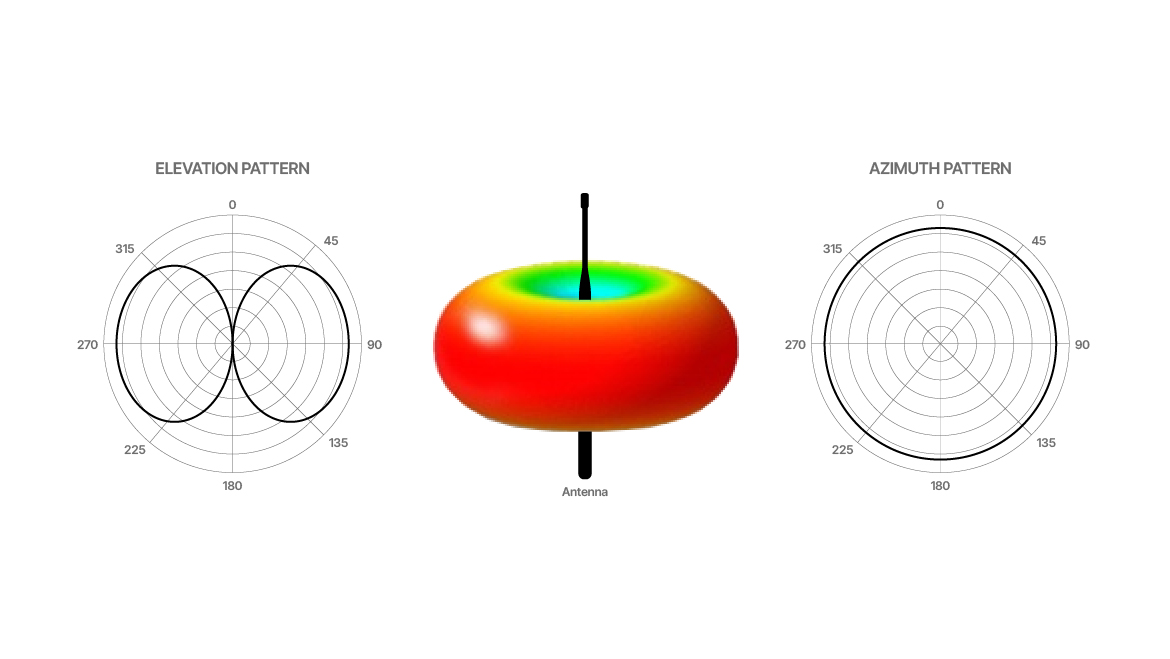
Although the antenna may be covered in plastic or rubber, the internal structure is metallic. This fact is important when considering spacing and placement.
Always maintain line of sight
The most important rule in wireless microphone installation is line of sight.
Line of sight means that, at any point during use, the transmitter should have a clear, unobstructed path to at least one of the receiver’s antennas.
This does not mean you must literally see the antenna with your eyes, but it does mean that:
- No large metal objects are blocking the path
- The signal does not need to pass through racks, walls or dense obstacles
- The signal path is as direct as possible
Why line of sight matters
Radio waves weaken as they pass through objects. Metal objects block RF very efficiently. Concrete, brick and human bodies also absorb RF energy. Every obstacle reduces signal strength and increases the chance of dropouts. This is especially important when working outdoors, where reflections cannot compensate for the lack of direct energy arriving at the antenna.
Height helps. Placing antennas higher reduces the number of obstacles between the transmitter and receiver. However, height alone is not enough if the antennas are blocked or poorly positioned.
Receiver placement challenges
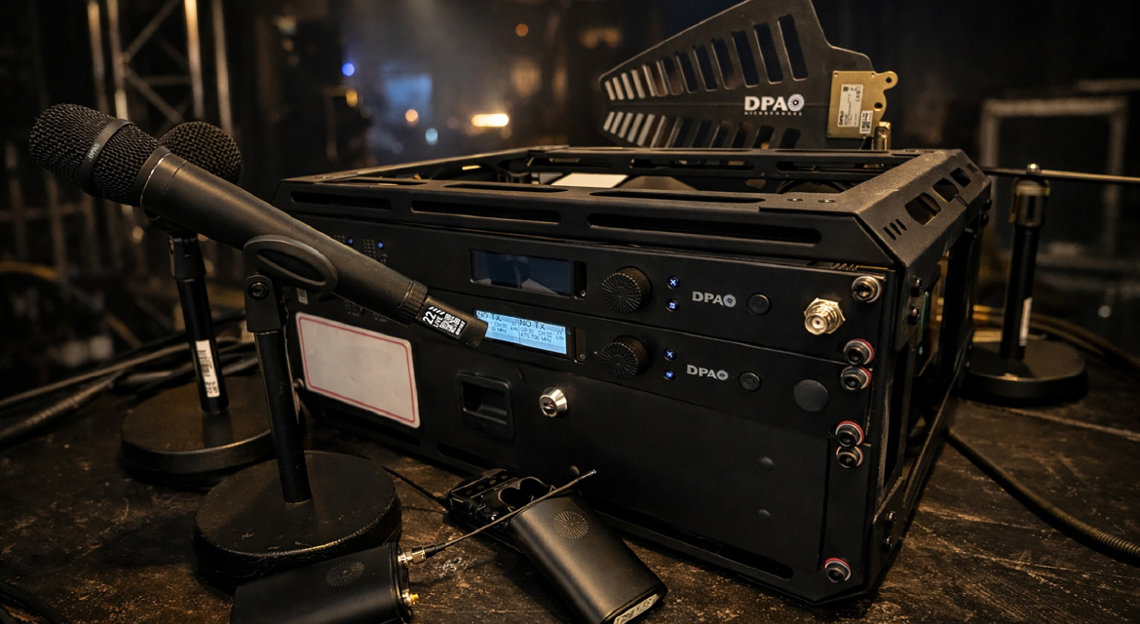
In many installations, receivers are mounted in 19-inch equipment racks. While this is convenient and professional, it introduces challenges.
If antennas are connected directly to the back of a rack-mounted receiver:
- The rack may block RF signals
- Metal rack rails can absorb or reflect RF
- There may be limited space to orient antennas properly
- Antennas may end up too close to other equipment
This is why direct rear-mounted antennas are often a bad idea in rack installations.
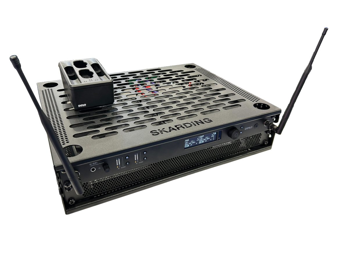
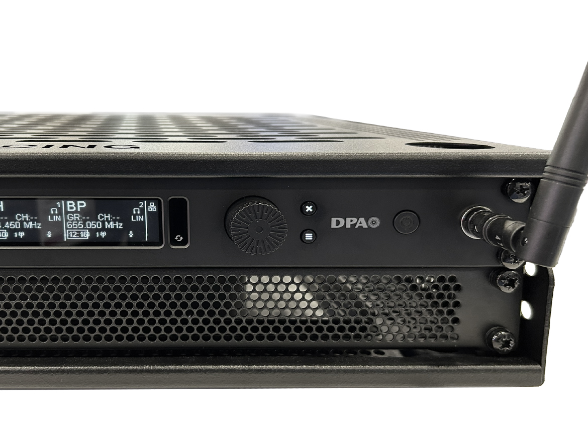
Using bulkhead adapters for better antenna placement
Bulkhead adapters are short RF cables that connect the receiver’s antenna inputs to a panel-mounted connector.
Their main advantages are:
- Allow antennas to be mounted on the front of the rack
- Allow antennas to be mounted outside the rack entirely
- Provide better control over antenna orientation
- Improve line of sight to transmitters
Many receivers already have marked holes on the front panel for bulkhead adapters, making installation straightforward.
Using bulkhead adapters lets you:
- Keep the receiver accessible for operation
- Position antennas where RF performance is best
- Avoid metal obstructions caused by the rack
Antenna spacing and metal surfaces
Antennas interact strongly with nearby metal. Poor spacing can significantly reduce performance.
Key rules for antenna placement
- Avoid placing antennas parallel to metal surfaces - If unavoidable, maintain at least 15–30 cm (6–12 in) of distance.
- Do not place antennas parallel to each other - Remember, antennas are metal internally.
- Maintain spacing between antennas - A minimum of 30 cm (12 in) between antennas is recommended. 50 cm (19 in) is the distance between panel front mounted antennas, which is a perfect fit for these types of antennas.
Proper spacing improves the effectiveness of diversity reception, which relies on comparing signals from two antennas selecting the best one.
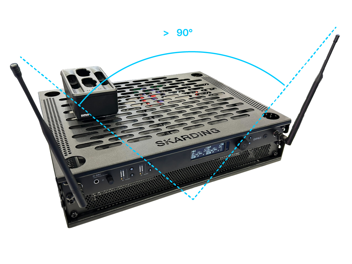
Understanding antenna polarization
RF signals are polarized, meaning they have a physical orientation, so:
- If the transmitting antenna is vertical, the receiving antenna should also be vertical
- If the transmitting antenna is horizontal, the receiving antenna should also be horizontal
If the transmitter and receiver antennas are misaligned, signal strength decreases.
Improving polarization reliability
To reduce polarization issues:
- Use a V-shaped or L-shaped antenna configuration
- This allows you to compromise a little so the antennas will better match the transmitter’s orientation
This is especially helpful when performers move, turn or change posture.
Human body absorption
Human bodies absorb RF energy. Water content in the body is particularly effective at absorbing radio waves.
This means:
- A bodypack transmitter worn on the back may be blocked by the user’s body
- Turning away from the receiver can reduce signal strength
- Crowded environments increase RF absorption and thus less direct signal strength
Best practices:
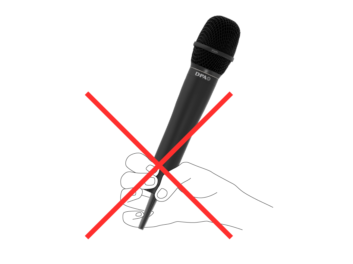
- Avoid placing the transmitter antenna directly against the body
- Position antennas to minimize body blockage
- Accept that some absorption is unavoidable, but minimize it where possible
- Do not hold a transmitter with the hand covering the antenna
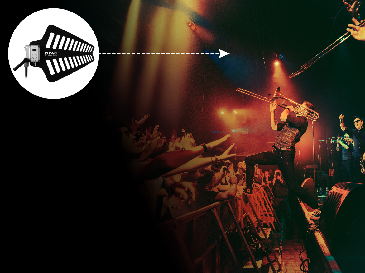
Audiences are challenging
Large audiences are one of the biggest challenges for wireless systems.
Each person absorbs RF energy. Hundreds of people can significantly reduce signal strength.
Use the height advantage
By placing antennas higher:
- Signals pass above the audience
- Fewer bodies block the RF path
- Overall system reliability improves
This is especially important in theaters, houses of worship and conference venues.
Many times, to achieve the best antenna positioning, you’ll need longer RF cables. Sometimes, to get the best performance, you might even need a different type of antenna.
RF gain structure and RSSI
Wireless receivers include a Received Signal Strength Indicator (RSSI) meter.
RSSI measures how much RF energy is reaching the receiver.
Understanding RSSI levels
- Low RSSI = weak signal, higher dropout risk
- Optimal RSSI = strong, clean signal
- Excessive RSSI = RF distortion and non-linear operation
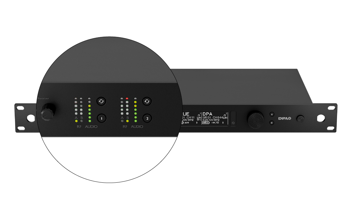
Most receivers indicate excessive RF with a red or top-level LED.
Too much RF may desensitize the receiver, and it may be even worse than too little RF.
Adjusting transmitter power
Many transmitters allow adjustable RF output power.
General guidelines
- Small indoor spaces: start at 10 mW
- Short distances: lower power is better
- Long distances: increase power carefully
If the transmitter is close to the receiver and RSSI is too high:
- Reduce transmitter power
If RSSI is too low:
- Move antennas closer
- Improve antenna placement
- Increase power only if necessary
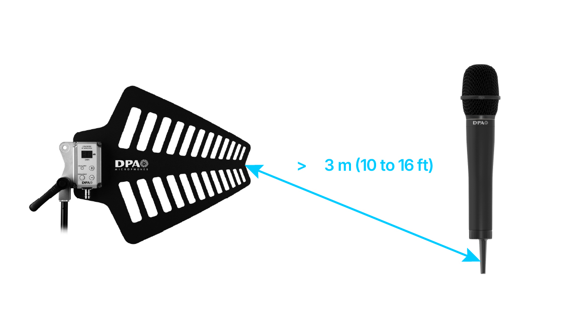
A better antenna position can be more beneficial than increasing transmitting power.
3–5 m (10–16 ft) between the transmitters and the receivers’ antennas is considered good practice.
Important note
You cannot hear RF distortion. Audio quality may sound perfect while RF performance is compromised. Always trust the meters and adjust accordingly.
Frequency selection fundamentals
Wireless audio quality depends on Carrier-to-Noise Ratio (CNR).
Carrier = your wireless microphone RF signal
Noise = all other RF energy in the environment
A healthy system maximizes carriers and minimizes noise.
RF spectrum and regulations
Wireless microphone frequencies are regulated by national authorities.
Typical ranges:
- 300 MHz to 3 GHz
Available frequencies depend on:
- Country
- Distance from TV stations
- Cellular networks
- Local RF congestion
Some locations offer many clean frequencies. Others are extremely crowded.
Tuning range matters
Older systems may offer:
- 12 MHz or 24 MHz tuning range
Modern high-end systems may offer:
- Hundreds of MHz tuning range
Wider tuning range means:
- More frequency options
- Higher chance of finding clean channels
- Better long-term usability
Working with multiple transmitters
When using multiple wireless microphones:
- Each transmitter needs a unique frequency
- Frequencies must be compatible
- Intermodulation changes depending on your gear and application
This topic is complex and covered in detail in frequency coordination theory.
Choosing frequencies: Two main methods
1. Quick setup (Groups and Channels)
Manufacturers pre-calculate compatible frequencies and group them.
Process:
- Turn all transmitters off
- Run Quick Setup on the receiver
- Receiver scans and suggests a group
- Select the same group for all receivers
- Assign unique channels
- Turn on and sync each transmitter one at a time
This is fast, simple and effective for small systems. You may have to repeat it for each of the receiver channels, leaving the previously calculated transmitters ON.
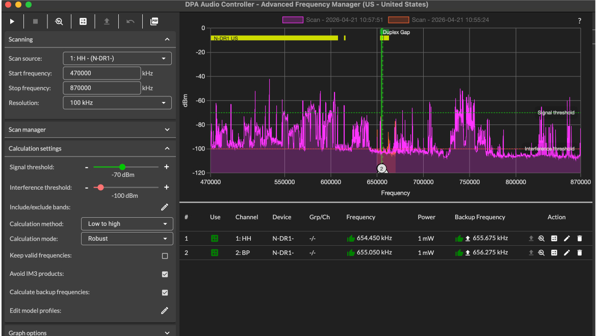
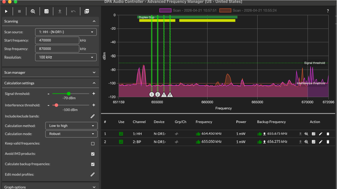
2. Frequency coordination software
Best for:
- Larger systems
- Complex RF environments
- Multiple models and brands used together
Typical process:
- Select receiver channels
- Scan the RF environment
- Analyze the scan
- Generate compatible frequencies
- Apply frequencies and sync transmitters
Using software from the same manufacturer allows you to seamlessly deploy the calculated frequencies.
Battery management: The final critical step
Wireless transmitters require power.
Battery types
- AA or AAA alkaline batteries
- Rechargeable AA or AAA batteries
- Dedicated rechargeable battery packs
Best practices
- Always carry spare batteries
- Keep fully charged spares
- Learn how battery indicators behave
- Do not rely on bars alone
- Replace batteries before critical events
Some batteries may drop quickly from “almost full” to empty. This is typical for standard off-the-shelf rechargeable batteries. Choosing batteries with predictable behavior can prevent failures during performances.
Final thoughts
Wireless microphones offer incredible flexibility, but they require careful planning and awareness. Good antenna placement, proper RF levels, clean frequencies and reliable power management are the foundation of a stable system.
If you follow the principles outlined in this article:
- Your system will be more reliable
- Dropouts will be minimized
- Users will have confidence and freedom
- You will be prepared to scale and grow
Wireless success is not magic—it is just understanding the challenges and following best practices.
Future articles will explore frequency coordination, advanced antenna systems and large-scale deployments in greater detail.